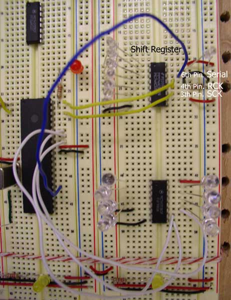
shift
register : MM74HC595
Product information MM74HC595:
http://www.fairchildsemi.com/ds/MM/MM74HC595.pdf
Application
_ how to interface a 74HC595:
http://www.kronosrobotics.com/an114/SMAN114.htm
References
:
References
from Yosef birnboim
http://www.birnboim.com/nyu/pcomp
http://www.birnboim.com/nyu/pcomp/techresearch/
Overview about shift
registers including diagrams and GIF animations:
http://www.eelab.usyd.edu.au/digital_tutorial/part2/register01.html
Links about serial
communications including USB and MIDI:
http://www.rdrop.com/~cary/html/serialportdocs.html
Serial
Communication: Shift Registers Research:
http://fargo.itp.tsoa.nyu.edu/~bb400/physicalComp/Serialresearch.html
StampWorks
Manual Version 1.2:
http://www.parallax.com/dl/docs/books/sw/exp/23a.pdf
pic code
for shiftout
http://microengineeringlabs.com/resources/pbpmanual/5_65-5_70.htm
SHIFTOUT
DataPin,ClockPin,Mode,[Var{\Bits}...]
Include Amodedefs.bas@
LSBFIRST
0(mode 0) operation: Shift data out lowest bit first. Clock idles low.
DEFINE SHIFT_PAUSEUS 100 : For example, to slow the clock by an additional
100 microseconds
--------------------------------------------------------------------
'****************************************************************
'* Name : SHIFT_REGISTER.BAS *
'* Author : HYUN JEAN LEE and JUNG EUN YOO *
'* Notice : Copyright (c) 2003 [select VIEW...EDITOR OPTIONS] *
'* : All Rights Reserved *
'* Date : 11/12/2003 *
'* Version : 1.0 *
'* Notes : *
'* : *
'****************************************************************
'LSBFIRST 0(mode 0) operation: Shift data out lowest bit first. Clock
idles low.
'DEFINE SHIFT_PAUSEUS 100 : For example, to slow the clock by an additional
100 microseconds
INCLUDE
"modedefs.bas"
'Include "Amodedefs.bas" : Include Amodedefs.bas@ --->
??????unable to open error
DEFINE OSC 20
DEFINE CCP1_REG PORTC 'Hpwm 1 pin port
DEFINE CCP1_BIT 2 'Hpwm 1 pin bit
DEFINE CCP2_REG PORTC 'Hpwm 2 pin port
DEFINE CCP2_BIT 1 'Hpwm 2 pin bit
DEFINE SHIFT_PAUSEUS 100
'The
following DEFINEs specify which timer, 1 or 2,
'to use with PWM channel 2 and PWM channel 3 for the PIC17C7xx devices.
'The default is timer 1 if no DEFINE is specified.
DEFINE HPWM2_TIMER 1 'Hpwm 2 timer select
DEFINE HPWM3_TIMER 1 'Hpwm 3 timer select
'
Define ADCIN parameters
DEFINE ADC_BITS 10 ' Set number of bits in result
DEFINE ADC_CLOCK 3 ' Set clock source (3=rc)
DEFINE ADC_SAMPLEUS 50 ' Set sampling time in uS
mstime
VAR BYTE
adval VAR WORD ' Create variable to store result
'adval2 VAR WORD
mstime = 0
' The actual pin numbers that you use below, doesn't matter,
' just MAKE SURE that it is properly updated
SerialData
VAR PORTC.6 'serial in - pin#12 on BX, pin#14 on 74HC595
Clk VAR PORTB.5 'shift register clock - pin#10 on BX, pin#11 on 74HC595
Latch VAR PORTB.7 'storage register clock (latch)-pin#11 on BX, pin#12
on 74HC595
NumberOfBits
VAR Byte 'the number of bits that you are sending to the register
counterVar VAR byte ' create counter variable
lf
con 10 ' line feed charactger in ASCII
cr con 13 ' carriage return character in ASCII
TRISA
= %11111111 ' Set PORTA to all input
TRISB = %00000000
TRISC = %00000000
ADCON1
= %10000010 ' Set PORTA analog and right justify result
Pause 500 ' Wait .5 second
NumberOfBits
= 8
Main
:
ADCIN 0, adval ' Read channel 0 to adval
HPWM 1, adval, 9000
while
mstime < 3 'flash me
high portb.6
pause 500
low portb.6
pause 500
mstime = mstime + 1
wend
pause
500 ' start program with a half-second delay
for
counterVar = 0 to 255 ' loop for each 'binary' number
LOW Clk ' set the clock low. sync it with the clock of the bx
LOW Latch ' set the latch low
' send the data out, in this case, we are send out the data of the 'binary
number'
' shiftOut(DataPin, ClockPin, NumberOfBits, Operand)
' bx24 : call shiftOut(SerialData, Clk, NumberOfBits, counterVar)
' PIC : SHIFTOUT DataPin,ClockPin,Mode,[Var{\Bits}...]
SHIFTOUT SerialData,Clk,0,[counterVar]
' display the number that we are counting
' debug.print cStr(counterVar)
pause 500 ' delay, so that we can actually 'see' something
high Latch ' set the latch high
next
goto MAIN
--------------------------------------------------------------------
Hookup:
BX pin
#23 to Ground
BX pin #21 to +5V MM74HC595 Output
pin # function pin # function
15 Parallel Out #1 LED #1
1 Parallel Out #2 LED #2
2 Parallel Out #3 LED #3
3 Parallel Out #4 LED #4
4 Parallel Out #5 LED #5
5 Parallel Out #6 LED #6
6 Parallel Out #7 LED #7
7 Parallel Out #8 LED #8
11 Clock
10 BX-24
12 Latch 11 BX-24 with 10K resistor to ground
14 Serial 12 BX-24
8 Ground
13 Ground
10 Power
16 Power
Reference
from http://www.birnboim.com/nyu/pcomp
Each LED
has a 220 ohm resistor connected to it in series. In
order to daisy chain the shift registers (which is the great thing about
them), send the serial out (pin 9) of register one, into the serial
in (pin 14) of register two, and so forth. Also, The clock and latch
should be sychnronized with either the BX or the previous chip.
The shift
register works from MOST SIGNIFICANT to LEAST SIGNIFICANT. This means
that the data in the 'one' column, is going to get bumped first, and
the '128' column last (if you are daisy chaining, then the 'one' gets
bumped to the '128' of the next register). It might help to draw a diagram
of how your data is going to flow, to make sure that you are sending
the right info to the right registers.
SUGGESTION:
You should have your 'sequence' of sending bits always fill up the entire
register(s) every time. This makes the bookeeping much easier and doesn't
require you to flush the registers everytime.
----------------------------------------------
BX-24
programming: This program sends data out to the shift register
and 'counts' in binary: 0000_0001, 0000_0010, 0000_0011, etc.
Option
Explicit
' The actual pin numbers that you use below, doesn't matter,
' just MAKE SURE that it is properly updated
Dim SerialData
as Byte 'serial in - pin#12 on BX, pin#14 on 74HC595
Dim Clk as Byte 'shift register clock - pin#10 on BX, pin#11 on 74HC595
Dim Latch as Byte 'storage register clock (latch) - pin#11 on BX, pin#12
on 74HC595
Dim NumberOfBits as Byte 'the number of bits that you are sending to
the register
Public
Sub Main()
SerialData
= 12
Clk = 10
Latch = 11
NumberOf Bits = 8
' create
counter variable
dim counterVar as byte
call delay(0.5) ' start program with a half-second delay
do
' loop for each 'binary' number
for counterVar = 0 to 255
' set the clock low. sync it with the clock of the bx
call putPin(Clk, 0)
' set the latch low
call putPin(Latch, 0)
' send the data out
' shiftOut(DataPin, ClockPin, NumberOfBits, Operand)
' in this case, we are send out the data of the 'binary number'
call shiftOut(SerialData, Clk, NumberOfBits, counterVar)
' display the number that we are counting
debug.print cStr(counterVar)
' delay, so that we can actually 'see' something
call delay(0.3)
' set the latch high
call putPin(Latch, 1)
next
loop
end
sub
-----------------------------------------------
|